
Examining the Suitability of E&P Major Accident Prevention Design
Abstract
Modern Oil and Gas facilities are designed to meet an extensive array of government legislation and international standards and are subjected to a range of technical and operational safety reviews and analysis to identify and reduce failure risk. By taking such an approach, residual risks can be demonstrated to be As Low As Reasonably Practicable, (ALARP) – this process is normally recorded through a Safety Case or safety report, reflecting good oil and gas practice.
Despite the use of recognised Exploration and Production, (E&P) practices provided in ISO, API, IEC, national standards and local in country regulations, major accidents are still occurring in the industry with an unacceptable frequency of intolerable business consequences. In addition, the differing regulatory compliance regimes between countries may not provide an equitable approach to operational and design requirements affecting safety and in particular the suitability of the risk management processes adopted.
It is generally accepted by E&P companies that significant major accident risk reduction is achieved at the design stage, to ensure that facilities are robust against system or component failure of Safety Critical Elements, (SCE). Moreover, regulatory bodies are increasingly expected by the public to adopt a robust intervention approach should operators continue to operate using an increasing set of operational deviations or with assets not in compliance with risk based inspection and testing requirements. In addition to the risk reduction achieved through the design, it is also understood that the human-machine interaction to respond to hazardous situations has a significant role to play in preventing the hazard occurrence and/or mitigating the magnitude of the consequence.
This paper will provide an overview of how the E&P industry provides robust “fail-safe” designs against Major Accident Hazards, (MAH) and possible differences in design practices between different E&P sectors, such as production platforms versus drilling rigs. The paper will also examine other major hazards’ industries and assess how their design requirements are configured to ensure that risk control systems fail in a safe manner and extrapolate these approaches to the E&P business. Case studies will be used to show how “fail-safe” design principles can be applied to the system design of a sub-sea well connected to a Mobile Offshore Drilling Unit, MODU during exploration drilling and also at the component level for the Blow-Out Preventer (BOP). The paper will discuss the findings from the case studies in the context of a providing a fail-safe design approach to reduce residual risks.
Introduction
What Do We Mean by a “Fail-safe” System?
Designing systems to be fail-safe, essentially means that when individual (or multiple) components fail, the overall system to be protected is not unacceptably degraded in its ability to operate or shut down safely. Specific preferential component failure modes can be designed into the system (or unwanted failures designed to be less likely) and a monitoring device or devices added independent to the main system to confirm the availability and accuracy of the safety devices, such as signaling position status devices on railways or real-time gas detector status monitoring on offshore facilities. The system to be protected is defined as one whose failure could directly lead or substantially contribute to the risk of harm to people – the fail-safe components are built into the safety barriers or “layers of protection”. Other targets can be incorporated within the design philosophy for the fail-safe system, such as environmental damage, business interruption or asset loss. The fail safe components also contribute to delivering defined system availability and/or operational envelopes.
The aviation industry has defined the goal for the design and certification of a fail-safe system in Regulation 14.CFR 25 1309 (1) as:
“Airplane systems and associated components, considered separately and in relation to other systems, must be designed so that the occurrence of any failure condition which would prevent the continued safe flight and landing of the airplane is extremely improbable, and the occurrence of any other failure condition which would reduce the capability of the airplane or the ability of the crew to cope with adverse operating conditions is improbable.”
The Regulation also specifies that warning information about the failure condition must be provided to the crew so that they may take the appropriate corrective action. These two design objectives relating to system failure requirements and component monitoring provide the basis for airplane certification standard practices and establish the approach to be used to determine the relative importance (and severity) of a system failure condition. A similar approach to fail-safe design is adopted in many other industries.
Based on the above general design objectives, the safety system adopted, often separate from the main system, is required to act according to a fail-safe (or safer) philosophy in one or more of the following ways:
- Where situations have escalated beyond the intervention of people to control the situation, to automatically shut down the whole system in a pre-defined safe manner for specified events – examples being full Emergency Shut-Down, ESD, of a process facility or a nuclear reactor trip.
- To provide warning of safety component failure and automatically isolate individual system areas with limited or no disruption to the main system operation, until a repair can be activated whilst retaining an adequate level of system safety reliability – examples being process train isolation, in-flight engine warning signals and redundant fault containment regions on train signaling systems.
- Particularly with mechanical or structural systems, to design for and incorporate, where practicable, well understood and preferential component failure attributes so as to minimise the risk after partial failure – examples being the residual strength of structural systems, where a single component failure does not lead to catastrophic global collapse of the system and the capability of drilling vessels to remain on location after a mooring line failure.
- Where fail-safe systems are completely destroyed in a catastrophic event and fail to function as required, they are supported by additional redundant and ideally diverse emergency recovery systems capable of being deployed to mitigate the final consequential business impact – examples being oil spill response offshore and flushing of boronated water into nuclear reactor cores to absorb neutrons and prevent runaway (uncontrolled) radioactive excursion.
Fail safe design components can include both active – such as hydraulically actuated ESD Valves (ESDVs) – or passive – such as weak-links in structural systems – and require distinct design approaches to provide functional reliability. For active systems the logic of the design is to allow uninterrupted operation (e.g. valves stay open) in normal operations but return the system to a safe status during an escalated threat scenario such as an uncontrolled hydrocarbon fire. Monitoring of the safety component reliability can be continuous using e.g. self-diagnostic tools applied to voting gas detectors that initiate ESDV closure. The functional performance and reliability of fail-safe components relies on either specific interval testing for e.g. ESDV closure, or requires planned inspection of passive systems as in e.g. mooring chains or structures.
A fail safe design that includes instrumentation and computer based elements should also be developed with automatic fault tolerant monitoring systems to ensure that critical components operate on demand at a reliability level commensurate with the potential failure consequences. Examples of this can be found in self-checking, redundant signaling controls for railway systems (which claim a 10-10 annual failure rate(2)) or multiple independent pressure trips on process plant. In redundant systems, it is often required to specify that should any critical component fail then the degraded system does not have an unacceptable hazardous failure rate on demand, until such time as the component can be replaced or repaired. Performance standards are then specified for the overall safety system based on a quantitative risk analysis, which should also consider any potential Common Mode Failure, (CMF).
Table 1 summarises the qualitative performance requirements aspects that are considered vital to a fail-safe, fault tolerant business critical system:
| Performance Requirement | Benefits |
| 1. Fail-safe design – system level | Inherently safer design principle complied with and consequences of safety device failure ALARP |
| 2. Fail-safe design – component level (no monitoring) | |
| 3. Fault monitoring – component level | Minimises demand failure rate for system and minimises business interruption from spurious sensor trips |
| 4. Condition monitoring – system and component level | Repair or replace component prior to dangerous failure (automatic system preferred) |
| 5. Redundancy in fail-safe systems | Reduced system failure rate and increased system availability, bounded by CMF |
| 6. Diversity in fail-safe system active components | Prevents CMF and mitigates risk to ALARP |
Table 1 – Fail-Safe, Fault Tolerant System Requirements
In an ideal world, the designer would desire to make the operated system and safety critical components 100% reliable. In reality, is it not possible to build a totally reliable fail-safe system, especially as the components suffer reducing reliability levels caused by either human design error and/or operational threats such as vibration fatigue, excessive heat, stray magnetic currents, excessive humidity and corrosion.
Due to the complexity of safety systems, the design of sub-system components should be assessed using failure assessment methodologies such as Failure Modes Effects and Criticality Analysis, FMECA(3). As a starting point, all failure causes are assumed to happen so that worst case scenarios are included to ensure that the design confirms the components within the system that are fail safe, and those components that are not may be redesigned depending on the magnitude of the consequences. When evaluating the complete safety system reliability, more detailed quantitative methods using Fault and Event Tree Analyis, FTA/ETA, are required to facilitate numerical risk comparisons between design options and configurations.
Examples of Fail-Safe Components in the Oil and Gas Industry
On hydrocarbon process facilities, the concept of isolation and blow down of the pressurised inventory is central to the operational safety philosophy. When a fault occurs in the process system, leading to uncontrolled hydrocarbon release or excessive pressure in the system, ESDVs – which are held open in normal operation with hydraulic pressure – are activated to close based on a signal from the protection sensors. Should the hydraulic systems fail due to leakage or other external damage, the ESDVs are spring loaded to fail to the closed position.
This design is therefore fail-safe because the production flow is contained and the platform is isolated from the well or upstream source of hydrocarbon flow.
However, from a blow down perspective the fail-safe design strategy is somewhat different. We require Blow Down Valves, BDVs to fail to the open position so that their safety function can be completed i.e. blow down the isolated inventory to atmosphere via the flare system. Therefore, BDVs are normally held closed by pressure and engineered to open when demanded on signals from the fire/gas system. Should the active hydraulic/air system pressures fail due to leakage/damage the valves are spring activated to fail-safe to the open position and allow blow-down.
Careful consideration is therefore needed during the facility Front End Engineering Design, FEED, stage to ensure that the development of the detailed Cause and Effects, (C&E) logic for each safety sub-system or component on the platform specifies the appropriate fail-safe position is for each hazard cause and is consistent with the requirements of the operational safety philosophy.
Providing Reliable Fail-Safe Components in the Oil and Gas Industry
The process ESDVs are activated by instrument based systems that must be reliable from a safety perspective whilst also not interrupting the normal operation by causing spurious trips (see performance requirements 3 and 5 of Table 1). Production availability is compromised when e.g. separator High High, (HH) trip levels are too sensitive or have no diversity in signal checking devices, which may lead to repeated and unnecessary production trips and shut-ins. Similarly, single voting and/or unreliable gas detector systems may, due to the poor fail-safe logic, lead to spurious production trips.
The fail-safe design approach adopted is to execute system functional reliability analysis, to ensure that only reliable trips in real hazard conditions are generated, thereby minimising as far as is possible the operational exposure to spurious trips. The benefits of multiple voting of trip sensors to confirm gas releases can be evaluated by using FTA during the design stage to assess the achieved reliability and production uptime gains versus the costs of installing and maintaining the voting system. In the oil industry, the results of analysing the safety device reliability is normally executed as part of the complete safety system evaluation using a Layers of Protection (LOPA) and Safety Integrity Levels, SIL, analysis(4) , that includes all relevant SCE reliabilities.
The fault trees in figures 1 and 2 provide a useful insight into how a fail-safe design approach to the safety device can provide suitable availability of the device whilst avoiding expensive spurious failures. Figure 1 shows a fault tree for single voting detectors, whereas Figure 2 shows the same arrangement, made fail-safe by implemented confirmed isolation and blow down for a 2 out of 3 voted detection system (usually denoted as 2oo3). In the multiple voting system, the rate of spurious trips has been reduced by almost a factor of ten – individual detectors cause system actuation at a frequency of 2.8E-06 events per year whereas the voted system experiences a spurious trip frequency of 1.2E-07 events per year (5)
 Figure 1: Spurious trip of Three Individual Detectors
Note that in this system any detector can actuate the protection.
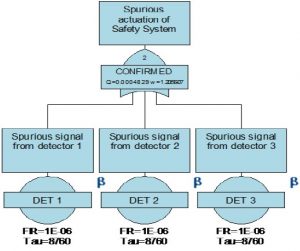
Figure 2 Spurious trip of Confirmed Detectors
Note that in this system the detectors are voted to actuate the protection.
Fail-safe Systems in the Railway Industry
The railway industry carries millions of passengers worldwide each year and requires reliable safety critical systems to minimize the probability of major accidents. The industry is generally regulated by strict safety regimes that usually specify safety systems incorporating fail-safe components as a core element. Typically, modern railway systems are required to operate with high integrity, computer based, interlocking activation devices that ensure signal controls go to red in the event of a failure – or when activated due to upstream hazards to the safe transit – stopping trains until the hazard is removed. A recent example of this principle occurred during the 2010 Japanese Tsunami when all trains were safely stopped and passenger safety assured. In Japan they also have the Urgent Earthquake Detection and Alarm System, (UrEDAS) system, which turns the railway signals to red and automatically facilitates braking on the bullet trains via the Automatic Train Protection, (ATP) system in the event of an earthquake event, thus making an accident less likely.
Fail-Safe Systems in the Nuclear Industry
In the nuclear power industry, safety is of paramount importance due to the risk to workers and the public of exposure to ionizing radiation. Therefore, fail-safe design principles have been employed to ensure that in fault conditions, the core of the nuclear reactor design logic activates an automatic reactor shut-down, without the need for operator intervention. The reliability of the fail-safe sensing and activation devices is required to be at an extremely high level, due to the consequential losses of a spurious shut-down that may write off the whole reactor and cause difficult and expensive emergency recovery actions. For example, there are various engineered shutdown systems at the Sizewell B Pressurised Water Reactor – the last nuclear power station to be built in the UK, which include:
- Boronated steel shutdown rods (primary fail-safe component) held out of the core by electro-magnets and energised on fail-safe circuit breakers controlling mechanical latches. On either a signal to trip the reactor or on loss of power, solenoids activate the circuit breakers that release the shut-down rods which fall under gravity into the core. The boron in the steel rods acts to absorb the neutrons in the core and mitigate the nuclear chain reaction.
- A secondary automatic back-up safety system that injects under gravity boron rich water (around 7000 ppm) into the nuclear core to “mop up” excessive neutrons and further mitigate the nuclear reaction.
The above automatic safeguards are designed to create a 30 minute grace time prior to any operator action and increase the fail-safe system reliability (refer performance requirement 4, Table 1). It should be noted that the 30 minute rule does not preclude operator action, but as the Three Mile Island incident showed, the ability of operators to take action under high stress conditions is low and often assumed to have a human reliability of no better that 10%(7) , which is unacceptably high for safe operation of a nuclear facility.
Fail-safe Systems in the Construction Industry
In the construction industry, an example of a fail-safe design is the provision of a crane overload protection system. To prevent a crane from lifting a load greater than its Safe Working Load, SWL, an Automatic Safe Load Indicator, ALSI, system provides an alarm in the crane cab to warn the driver to stop the lift. Should the crane operator ignore the alarm and try and exceed the load limits (normally 110% of SWL), a fail-safe system automatically trips the brakes on the crane and interrupts any hoisting or slewing motions. This safety feature is especially useful in circumstances where a load may become snagged on an obstacle which prevents it being lifted further. Additionally, for cranes operating in a nuclear plant, it is usual to have dual load paths and active ASLI systems actuating redundant breaks to meet the stricter safety targets.
Fail-safe Systems in Consumer Products
Even in consumer products we are now seeing the extensive use of fail-safe features. For example, domestic grass mowers are fitted with a power supply handle which will cease to operate if the grip applied the handle is released intentionally or by accident, thus making it a fail-safe feature of the machine.
Fail-Safe Designs in the Offshore Drilling Industry – Dealing with Worst Case Scenarios
The recent Macondo incident has demonstrated that making a safety argument based on individual barrier failure probability, whilst satisfying a theoretical risk matrix or QRA approach, carries little mitigative defence in law.
To mitigate against latent defects and operational practices that could degrade safety barriers, to the extent that using numerical failure rates alone cannot demonstrate effective control of MAH risks, a fail-safe design approach is vital to ensure an ALARP demonstration. Requiring information about how robust the design is to any given component failure is a recommended qualitative method for the executive board to apply when sanctioning project risks in addition to e.g. a traffic light and/or risk acceptance criteria approach.
The operator’s technical/risk management team has to be satisfied that any engineered system provided for e.g. well control incorporates, so far as is reasonably practicable, a fail-safe strategy. Where designs can be modified to adopt/maximise the fail-safe approach, whilst still providing e.g. a positive NPV, then those proposals should be developed further and made part of an ALARP Cost Benefit Analysis, CBA, to ensure a transparent decision process to accept/reject any design changes. Note that such changes should focus on physical engineered barriers, combined with enhanced procedures or increased supervision of safety critical tasks to ensure the fail-safe component reliability is achieved in operation. The following sections of this paper describes fail-safe issues for a number of failure scenarios during drilling operations that should be considered
Exploration Well, Major Accident Scenario 1 – Loss of MODU Positioning Combined with a Failure to Disconnect the Riser
Exploration wells, in particular those in harsh environment/deep-water, are often drilled using a dynamically positioned vessel which require a satisfactory level of integrity of the riser, Lower Marine Riser Package, LMRP, BOP and conductor system to cater for accident scenarios where large riser offsets occur. Where moored systems are used, or a hybrid moored/DP system, these can also suffer single or multiple mooring failures in extreme weather and/or DP failure and subsequent excessive discursion above the sub-sea well position.
Applying the fail-safe design approach to cater for the scenario of large MODU offsets whilst still being attached to LMRP requires a structural analysis of the ultimate strength (failure capacity) of the key components and connections that make up the barriers. The possible system integrity failure scenarios, as shown in Figure 3, are:
- The riser fails at the Lower Flex Joint, LFJ
- The riser fails at a transition connection – usually just below the transition pup connection above water.
- The LMRP or BOP connectors fail
- The conductor fails
If scenario 2 occurs, the riser will collapse and possibly damage the BOP, making well re-entry and repair extremely difficult. If scenarios 3 or 4 occur, you could assume that the cost of drilling a replacement well is a likely consequence. The worst case consequence occurs when hydrocarbons are present in the well leading to an environmental incident, or should hydrocarbons ignite at the drill-floor a catastrophic fire and possible loss of life and MODU. One of the recommended actions prior to drilling into the pay-zone is therefore to test the riser disconnect system when it is practicable to do so.
If scenario 1 occurs, the MODU drifts away from the well with the riser attached. The consequences are significant MODU down time, partial riser replacement, repair to the LFJ and subsequently re-attaching the riser – the well remains intact. If we can engineer the system so that failure occurs at this location, then we engineer a fail-safe or safer design.
In order therefore to produce a fail-safe design, an ultimate collapse analysis can identify the relative strengths in the system components to ensure that the riser fails at a location that minimise the release probability of hydrocarbons and mitigates asset damage and related project cost/schedule impacts. A recent study(8) has investigated just such a worst case and found a range of component ultimate capacities – varying depending on the water depth, weather conditions at the time and specific component types used as shown in Table 2.

Figure 3 Riser, LMRP, BOP, and Conductor System – Exploration Well
| Component | Capacity Failure Mode | Survival/Rated Capacity |
| Riser Couplings | Tension | 2.37 |
| Riser Pipe | Tension | 1.16 |
| Lower Flexible Joint | Tension | 1.48 |
| Wellhead Connector | Bending | 1.62-1.72 |
| Tensioner Hardware | Bending and Shear | 1.5 |
Table 2 – System Component Failure Capacity – Exploration Wells
It is clear from this analysis the fail-safe mode – failure at the lower flex joint cannot be guaranteed and changes could be engineered to ensure that the riser pipe transition piece would not fail first – this satisfies the fail-safe performance requirement 1 in Table 1.
Exploration Well Major Accident scenario 2 – Well Kicks and Sub-sequent Blow-out
One of the main challenges in drilling new or re-entering existing wells is to provide the primary safety barrier using mud-weight to prevent the well pore pressures at the hydrocarbon pay-zone entering the well prior to making the well complete for e.g. test production. If the mud pressure is “too high” the formation could be fractured leading to escape of mud into the rock and possibly the sea. If the mud pressure is too low, the result can be an excessive amount of hydrocarbons entering the well, possibly leading to an uncontrolled blowout at the drill floor area, if the Blowout Preventer, BOP fails.
The BOP has been designed as the secondary safety barrier against loss of well control/blowouts and acts to isolate the rig from the well at the well-head to allow for evaluation of the incident. If required the well can be killed and abandoned using high density cement to seal (plug) the pay zone.
When we examine the basic design of a BOP we discover, perhaps not surprisingly given the hazardous nature of drilling, that there are several safety features embedded into the design. Figure 4 depicts a typical BOP arrangement in terms of the control systems that activate the components of the safety system, indicating redundant hydraulic control pods, denoted as Blue and Yellow. These control pods supply hydraulic fluid via separately routed umbilicals to provide the motive force to seal the well fluids in the various casing annuli via closing annular ram seals – this is often done as a precautionary measure to control unexpected well kicks recorded at the mud-pits on the rig. Should the umbilical signals fail the local hydraulic accumulator stacks can be used as the motive force to activate the BOP rams.
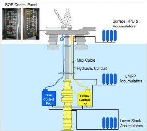
Figure 4 – Typical Control Arrangements in a BOP
Should the annular rams fail or the kick be sudden and massive leading to significant hydrocarbons on the drill floor, then a Blind Shear Ram, BSR, can be manually activated at the BOP control panel on the rig to cut and seal above the drill pipe and isolate the well below the BOP.
Immediate observations of this system may query whether a system with three separate accumulator stacks (multiple redundancy for single failure) to actuate a single solenoid valve on the pods (as shown in Figure 9), thereby engaging the closure rams that seal off flow, can be regarded as a balanced design. In addition, the manual activation of the RAMs may not provide the required reliability in emergency situations.
Operation of the BOP Stack
Figure 5 presents the BOP in more detail and shows each of the key safety features in the design. The well head is shown at the bottom of the figure attached to the wellhead connector upon which sits the BOP stack and the Lower Marine Riser Package, (LMRP) as indicated.
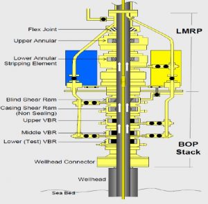
Figure 5 – Typical Detail of a BOP Showing Various Safety Features
The BOP Stack contains the design features which are intended to operate to seal the well in the event of a problem. The Variable Bore RAM, (VBR) is designed to constrict the drill pipe and thus stop the flow beyond the VBR, note a Lower (Test) VBR; Middle VBR and Upper VBR are provided and are all essentially similar in design as indicated in the Figure 6. In addition to the VBRs the BSR is also provided to seal the drill pipe by shearing it in two to halt the flow as in Figure 7. Analysing the BOP ram configuration and activation devices, using a FTA/ETA, may quantify the extent to which a design exhibit critical lower reliability failure modes and is therefore not fail-safe and/or fault tolerant.
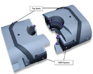
Figure 6 – Typical Arrangement for a VBR
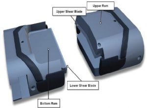
Figure 7 – Typical Arrangement for a BSR
A common feature between these rams is the mechanical locking mechanism which is used to lock the RAMS by mechanical latching so that in the event of a loss of hydraulic pressure the RAMS stay closed. This is a fail-safe feature satisfying performance requirement 6 of Table 1.
Lower Marine Riser Package, LMRP
The LMRP contains the upper annulus preventer which is used to seal the annulus around the drill pipe as shown in Figure 7 and the control packages which are used to initiate the safety devices on the BOP Stack.
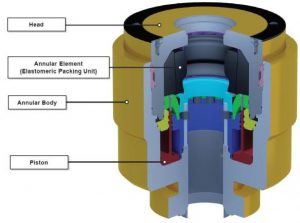
Figure 8 – Typical Arrangement for the Upper Annulus Preventer
How is the BOP Controlled to Operate Safely?
The control architecture of a typical BOP is presented as Figure 9. This typically indicates two separate control pods denoted as Yellow and Green, but with identical architecture within each pod to convert electrical power into hydraulic control of the BOP safety features. In the unlikely event of a loss of hydraulic pressure or control from the surface, due to say an immediate explosion at the drill floor as occurred at Macondo, an Automatic Mode Function, (AMF) is provided as an emergency back-up (satisfying the fail-safe performance requirement 5 in Table1) to activate the high pressure BSRs and associated mechanical locks. The normal arrangement is that the solenoid valve is energized from the main battery to activate this shearing system.
Are the BOP Components/Systems Fail-safe?
Figure 9 presents a possible failure scenario of safety critical components in the BOP well control system, some of which have previously occurred in the drilling industry. If for example the 27 volt battery is depleted on the blue control pod the AMF will not operate the solenoid valve via this pod and we are left with only the yellow pod available. As the blue pod safety function cannot now be completed, if demanded, it is essential that battery failure is subject to automatic or very frequent monitoring otherwise the design may not meet the fail-safe criteria (see performance requirement 4 Table 1). If we are relying on interval testing, it may be likely that the normal operational procedures do not test and detect the battery failure mode until say a scheduled test of the battery pack, which may occur only every 6 months – in such a condition the battery failure will be assigned in a FMECA as Fail Dangerous – Undetected and be in breach of the fail-safe design approach. (Refer the Annex for a description of various failure modes).
The battery component now becomes a Safety Critical Element, (SCE), according to the standard definition that failure could significantly contribute to a Major Accident occurring. Without real-time knowledge of the health of the battery we cannot be certain that our AMF safety feature will work when demanded but we still have our back-up control route through the Yellow pod so all is not lost. However, if we also assume that the back-up system has a solenoid valve failure (as depicted in the example in Figure 9) then the safety function of the Yellow control pod cannot be carried out even with a charged battery – both the yellow and blue control systems are then in an unrevealed failure condition.
The activation reliability of the main or back-up systems, even if all critical devices are functional, relies on operator intervention at the BOP panel in the event of a major loss of containment to activate either the Annular Preventer or the Emergency Disconnection System from the control room – this can have a high error rate of 10% or more(7) as discussed earlier. It could therefore be argued that any well kick monitoring devices (e.g. HITEC or Serry Sun) that provide the operator a prompt for taking such manual action should be developed according to the fail-safe principles.
Ultimately, the fallback position is the automatic actuation of the AMF in the event of support system failure, or as occurred in the Macondo incident the automatic actuation of the high pressure shear system which uses stored accumulator pressure as a means to activate the BSR.
To fully understand the relevance of these failure modes and others that may exist within the system, the usual practice is to carry out a FMECA(3) . For failure modes identified as fail-dangerous undetected, specific strategies can be implemented to either carefully monitor the SCE to satisfy a risk acceptable Performance Standard or preferably ensuring that fail-dangerous modes are designed out at source. The frequency of testing the battery/solenoid valve activation sub-system is therefore a critical Performance Standard and may be calculated using e.g. a fault tree analysis.
How Could a Typical BOP Design be Improved to Utilise Fail-Safe, Fault Tolerant Design Principles?
From the examples cited in this paper there are several ways in which a typical BOP design could potentially be improved to meet fail-safe design principles:
- Battery failure -the design could be amended to ensure that solenoids are held energized and only when de-energised activate the required protection function. In this way problems with batteries would be fail-safe in the sense that protection would be activated. Obviously a reliable, redundant warning system of impending battery failure would be part of this solution to ensure that operators have sufficient time to stop the automatic solenoid activation and avoid activating the BSR which would cause significant damage to the tubing/casings and subsequent delays.
- Solenoid valve failure – additional redundant solenoid valves could be added included in each control pod system configured so as to improve their reliability on demand.
- In addition to the specific issue of solenoid valve redundancy, we could ensure that we have a balanced design for the complete safety system, verified by FTA/ETA, to ensure suitable redundancy or diversity in all active fail-safe components.
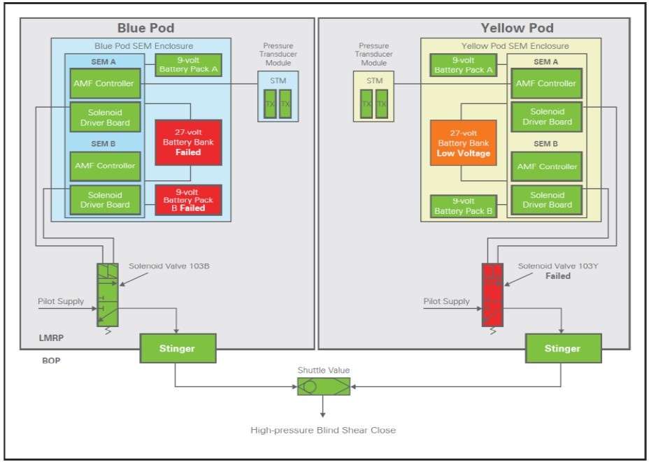
Figure 9 – Typical BOP BSR Controls and Possible Component Failures
Concluding Remarks
This paper has reviewed how various industries have adopted fail-safe and fault tolerant systems and components as an essential part of their design strategy. Examples from the drilling industry have suggested potential improvements required at the system level – to cater for loss of integrity of the riser, LMRP and BOP elements, and at the component level – to ensure that the BOP contains a well-kick.
The message for the oil and gas industry is to ensure all SCEs (systems and components) that are required to prevent or mitigate a major accident from occurring are designed as fail-safe and fault-tolerant as far as is reasonably practicable.
Annex 1 – Equations Relating to Failure Modes
In any system there are four types of failure modes(6) and the failure rate of any given item can be sub-divided as follows:
λ SD = Safe Failures Detected Failure Rate
λ SU = Safe Failures Undetected Failure Rate
λ DD = Dangerous Failures Detected Failure Rate
λ DU = Dangerous Failures Undetected Failure rate
Total Failure rate, λ Total = λ SD + λ SU + λ DD + λ DU – Equation 1
An alternative metric is the Safety Failure Fraction, (SFF) for a system or component which is given as:
SFF = (λ SD + λ SU + λ DD) / λ Total – Equation 2
or alternatively derived as (λ Total – λ DU) / λ Total – Equation 3
References:
(1) AIRWORTHINESS STANDARDS: “TRANSPORT CATEGORY AIRPLANES”, Code of Federal regulation (US), 14.CFR. 25 1309, PART 25 – Subpart F – Equipment. – General.
(2) “Fault Tolerant Fail-Safe System for Railway Signaling”, A Chakraborty, WCECS, October, 2009
(3) “Failure Modes Effects Criticality Analysis”, FMECA Military Standard, MIL1629.
(4) IEC 61511 “Functional safety instrumented systems for the process industry sector (all parts)”
(5) Isograph Software Warrington, Fault Tree +
(6) IEC 61511 “Functional Safety of Electrical/Electronic/Programmable Electronic Safety Systems (all parts)”
(7) “A data-based method for assessing and reducing human error to improve operational performance”, Proceedings of the IEEE 4th Conference on Human Factors in Power Plants, California, Jerry Williams, June, 1988.
(8) “Riser Failure Study IDs Well Control Weak Links”, Sonowane, Kosa, Campbell, 2H Offshore, Deep-water Drilling, March/April, 2012
Author: Roland Martland
Latest Developments in Safety Case Regime Singapore